


No Items in cart
Backup Power for Heating Boilers Using KS 2000iS and KS 2000iG S Generators
Articles
October 5, 2023

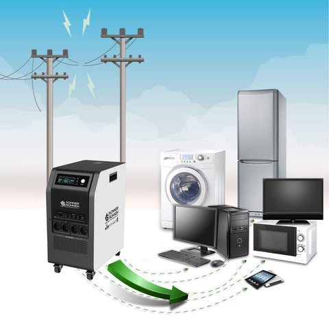
A generator for a boiler has become an essential component in modern heating systems. Even if the energy source is gas, firewood, etc., electricity is still required for control units, circulation pumps, and other components. Therefore, it is critically important to properly design the backup power supply for your heating system.
Since heating systems require a TN grounding system with a grounded neutral conductor (similar to what is present in the public power grid), devices like a gas boiler cannot be connected directly to a generator outlet without proper preparation.
The heating system can be powered either as part of the house's overall backup power system or through a dedicated switching device specifically designed for the heating system.
You can learn more about how to provide emergency power to a heating system as part of a whole-house backup power solution in our informational materials available on our website.
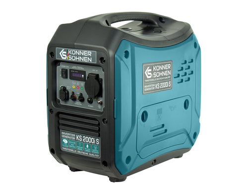
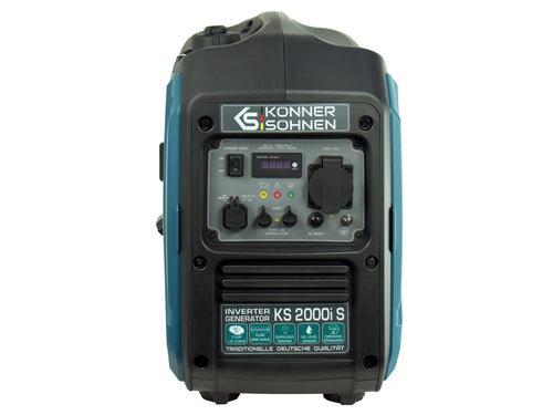
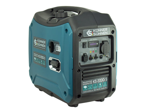
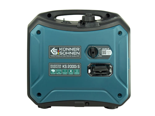
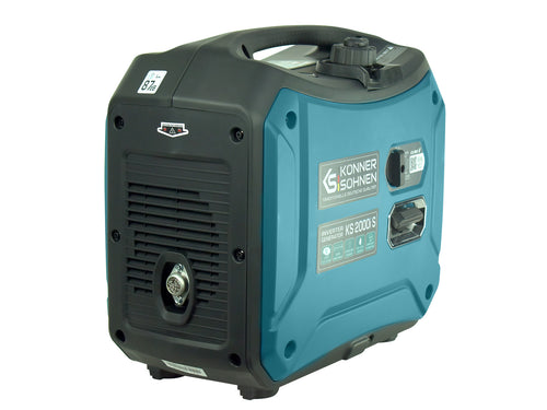
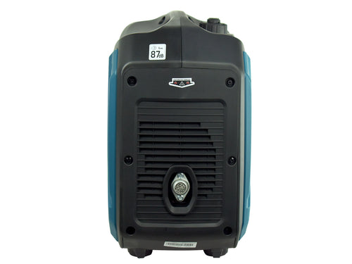
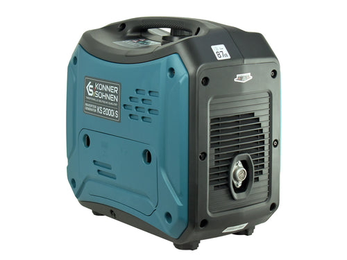
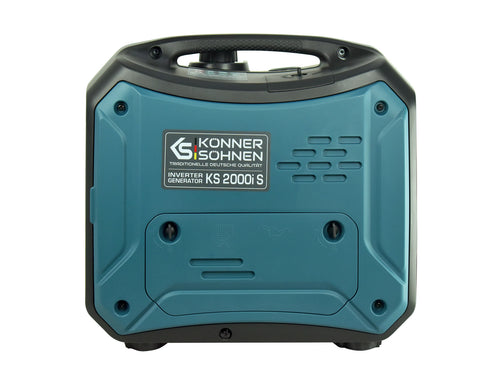
In this article, we present a solution for backing up the power supply to the heating system (boiler and related components) using affordable inverter generators from Könner & Söhnen – KS 2000iS and KS 2000iG S. Their rated power output of 1.8 kW is sufficient for a gas boiler with circulation pumps, a solar thermal system, and other heating components. This ensures your home stays warm even when it's freezing outside.
Modern heating systems usually include electronic control modules that require a pure sine wave voltage. This requirement is typically stated by manufacturers of heating and solar thermal water heating systems.
A comparison of voltage (yellow) and current (green) waveforms when operating an electronic device from an inverter generator (left) and a conventional generator (right) clearly shows the difference:


Advantages of Inverter Technology
The voltage waveform is one of the most important parameters of electrical power. While it is standardized in public grids (THDU ≤ 8%, individual harmonic/U1 ≤ 5%), this is not the case for emergency generators. A conventional generator’s voltage regulator controls only the effective voltage value but cannot regulate the waveform, which may cause issues with nonlinear loads.
Electronic devices can distort the voltage waveform and introduce harmonics, potentially harming the devices themselves. For this reason, most boiler manufacturers explicitly require a pure sine wave power supply, like that of the public power grid.
Inverter generators such as the KS 2000iS and KS 2000iG S produce a stable 230V 50Hz pure sine wave and are capable of maintaining it under load. These models are also fuel-efficient (an ECONOMY MODE is available for lighter loads), making them an excellent choice for backup power for your heating system or solar controller.
Recommended Wiring Diagram

The cable to the power input point is considered part of the generator’s external wiring. The TN system is only established when the generator is plugged into the power inlet. A Schuko plug on the generator can be reversed, but this does not affect the phase and neutral arrangement for the heating system, as these are defined by the power inlet on the switching device.
The N (neutral) and PE (protective earth) conductors from the generator are connected together at the switch and linked to the home’s grounding system. This builds a TN system with a grounded neutral, similar to how power transformers operate in public utility networks.
Important safety note:
Operating a generator with bridged N and PE conductors without grounding is prohibited due to personal safety risks. DIY cables with a bridge between N and PE are also strictly forbidden. The installation must be designed in a way that even a non-specialist can connect the generator safely and correctly, and the wiring diagram provided above ensures this.
The grounding screw on the generator must be connected to the main grounding busbar of the house or to a dedicated grounding rod using a flexible 6 mm² copper cable. This protects against short circuits inside the generator in case of a PE conductor failure in the cable to the power input.
DISCLAIMER:
This informational material is intended to familiarize users with the functions of Könner & Söhnen generators and their possible applications. It should be considered as general recommendations only and must be adapted to the specific circumstances and conditions of your installation. The actual installation must be carried out in compliance with all relevant standards and regulations. We assume no liability for improper installations and their consequences.
Products in article
- Voltage, V: 230
- Max power, kW: 2.0**
- Nominal power, kW: 1.8**
- Engine start: Manual
- Outlets: 1 x Schuko 230 V
- Voltage, V: 230
- Max power, kW: 2.0
- Nominal power, kW: 1.8
- Engine start: Manual
- Outlets: 1 x Schuko 230 V
Other articles